Installing a Motherboard - How to Install a Motherboard
With our step-by-step picture guide, installing a motherboard is a breeze even if you're a total beginner. Learn how to install a motherboard in a case now.
Before installing a new motherboard, you should have already done all of the following:
If you haven't installed the CPU, cooler or RAM, you can click on the above links for their installation steps.
Even if your computer case has a CPU cut-out (to allow for CPU installation), it's still easier to install the above parts first before squeezing your motherboard into the cramped quarters of a case.
1. Install I/O Shield (Metal Back Plate)
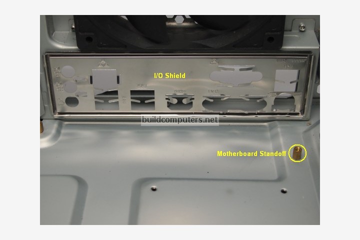
All motherboards should come with a metal plate with cutouts for the back connectors and ports. This metal plate is called the I/O shield (Input/Output shield). The I/O shield snaps into the back end of computer cases - No screws needed.
Before installing a motherboard in a case, you have to make sure the I/O shield is inserted in the correct direction. If your I/O shield is the type with tiny protruding bits, they should point towards the insides of the computer case (see image below):
2. Install Motherboard into Case
Now let's turn our attention to the motherboard standoffs (circled in yellow above). Also known as motherboard pegs, these brass-colored objects are used to secure your motherboard to the case.
Some computer cases come with motherboard standoffs pre-installed, while for others you will have to screw in the standoffs yourself. Remember to tighten the pegs with a pair of pliers instead of just using your thumbs.
Installing a motherboard: Lower your motherboard slowly into the computer case such that
- the motherboard holes align with the standoffs on the case
- the rear motherboard ports line up with the I/O shield
How to install a motherboard: Grab a screwdriver and fasten your motherboard to the computer case with the screws that come with your computer case (see image below). For a motherboard to be properly secured, it should be fastened with at least four screws.
3. Connect Front Panel Connectors to Motherboard
In order for the power button, reset button, front USB ports, front audio ports and LED lights of the computer case to work, you will need to plug their front panel connectors into the front panel header on the motherboard.
Manufacturers tend to use abbreviations to label front panel connectors and headers. When installing a motherboard, it's important that you know what these abbreviations stand for:
- H.D.D LED, HD - hard drive LED
- POWER LED, PWR LED, PLED, - power LED
- POWER SW, PWR SW, PW - power switch
- RESET SW, RESET, RES - reset switch
- SPEAKER, SPEAK - internal PC speaker
- HD AUDIO, AC' 97, F_AUDIO - front panel headphone and microphone jack
- USB, F_USB - front panel USB port
Moving on with our motherboard installation guide, let's take a look at the front panel connectors:
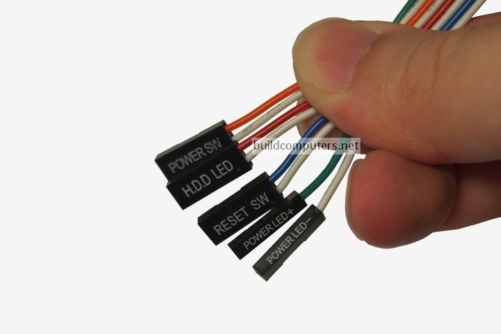
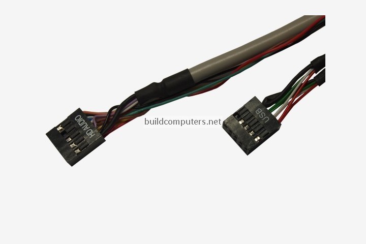
How to connect front panel connectors to motherboard: Locate the F_panel front panel header which is a cluster of small upright pins on your motherboard (see image below). Now it's a good time to take out your motherboard manual if you need help finding this header.
The front USB and audio connectors are the easiest to connect: Not only are they are larger in size, but they also have a foolproof design such that you can only connect them in one direction. The only thing to note is that if you have both HD AUDIO and AC' 97 audio connectors, always choose HD AUDIO for better sound quality.
The power switch and reset switch connectors will work in any orientation so no worries there.
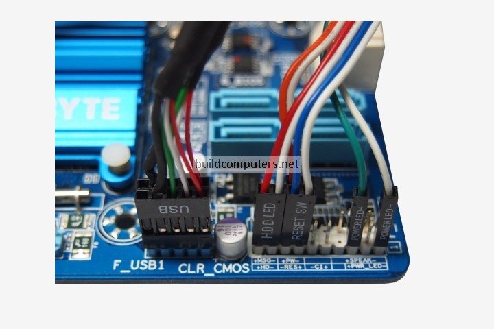
The power LED and hard drive LED are the biggest headaches you will encounter when installing a motherboard. In order for the LEDs to light up, you will need to plug in a positive connector into a positive header pin and the same goes for their negative counterparts.
While the positive and negative pins on motherboard are always labelled (see image below), it's common to find front panel connectors without any positive and negative labeling. As a general guideline, the connectors with white/black wires are positive and the connector with colored wires are negative. In case the LEDs don't light up, simply swap the positions of the connectors.
4. Connect Case Fans to Motherboard
Now we're down to the last step of installing a motherboard and it's a simple one: Connecting the computer case fans to your motherboard.
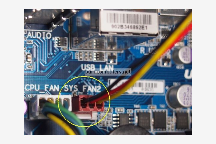
All you have to do is take the case fan's connector (circled in yellow below) and plug it into a 3-pin or 4-pin fan header on your motherboard. This header is often labelled as SYS_FAN or PWR_FAN.
No worries if you don't have enough fan headers for all your case fans - We will show you how to power them with molex connectors in a later section of this guide.
HOW TO BUILD A COMPUTER
- Should I Buy or Build a PC?
- Parts to Build a Computer
- Installing a CPU Processor
- Installing a CPU Fan
- Installing RAM Memory
- Installing a Motherboard
- Installing a Power Supply
- Power Supply Connectors
- Installing a Hard Drive
- Installing a DVD Drive
- Installing a Graphics Card
- Computer Cable Management
- Computer Cable Connections

